24 décembre 2008

Sticks

Finally I received the sticks. There are from a Futaba FC-18 transmitter. Their price is reasonable (approx 50€ each, dec 2008).

Quality seems good. They are accurate et pretty smooth. Stick have 5k potentiometer, and trim have 10k potentiometer.

Trims can easily be removed from the stick. They are just fix to the stick frame with two screw.

21 décembre 2008

Transmitter box

Sorry for the bad quality, it is still a very early draft.


I intend to make it as ergonomic as possible while keeping it simple. Both side are rounded to be confortable in hands, and below the low cover is embeded leaving some space for fingers.

As you can see, there is no trim. The idea is to use "auto trim" as described by jef raskin who pioneered the human-computer interface at Apple (not less!). The principle of autotrim is simple: move the stick in the position and press the button. Then release the stick. But problem of autotrim is their lack of accuracy when you need small changes. For that, the coding wheel (above the stick) can be used to control the small offsets. It will works like this: first select which trim you want to set, by pressing on of the button (corresponding stick must be released), and then fine tune the trim with the coding wheel. This is fairly simple and should be ergonomic, everything falling under the hand.

Between the sticks, there is the lcd display (The first version will probably have a smaller size than the one presented). The switches below the sticks, and the coding wheel will be input for the lcd. One or several leds above the lcd will monitor the battery status.

and why not multi-microprocessor ?

After having play just a bit with the AVR32, I am not convinced. This chip looks young, there are not many people developping on it, it is still in an early phase for Atmel, can't found that many examples, it requires the use of an OS like freeRTOS, flashing under USB and linux is a boring, etc...
To stay with simple 8 bits chips, I am thinking to use a multiprocessoir architecture, like mrdunk robot each processor dedicated to its own task, all communicating through i2c. The drawback of this, is that it add more electronic, but the good thing is that it is more flexible, new feature can be added to the transmitter without worried too much about performance and impacts on the other components.

14 décembre 2008

Next phase: AVR32

I have started to play with the AVR32 chip on the board from alvidi. Well, it is not as easy as arduino board, or AVR 8 bits chips. First, there is no "pure" avr-gcc" available, but a gnu-toolchain version made by Atmel. As I am working under Linux, I used the Linux version. You can forget the simple "PORTB" or "DDRB" register names that are used on AVR8. Names are mostly different ahd hardly understandable. But Atmel provides a software development kit that brings basic libraries for most devices available on the AT32UC3A.

One good thing with this chip, it that it can be flashed directly through USB. It took me some time to find that I should install the "flip-3.2.1" software available on Atmel site to do this job. But there is still a problem: this software is not up to date for its linux version, so the flip program itself can't be used. Fortunately, there is in the package another program called "batchisp3" that can be used by command line. But the bad news is that this version is not working correctly with last Ubuntu 8.04. So to flash the AT32UC3A1512, you will need to hack it. I found an interesting thread on avr-freak: you'll need an Hexadecimal editor, and replace /sys/bus/usb and /proc/bus/usb instead of /dev/bus/usb. Hopefully, once this hack done, it worked.

The first application I tried was to light some leds. For this , I used the GPIO local_bus_address example delivered in the Software development kit. I modified the Makefile to take the hacked batchisp3 for download, and added the full path for the .elf target as batchisp3 need the complete path to find the file.
After the traditional make to compile, or better make clean and make, it need a "sudo make isp program run" to flash and run the software on the target. The "isp" option specifies to use batchisp3 program instead of avrprogram, and "program" do the flash. But don't forget also the "run" otherwise the application will never run.
Ouf.
Now the next phase will be to run FreeRtos on the target. Currently it does not compile due to some bad header files. The problem is known, but there is not yet good solution.

06 décembre 2008

Some screenshots

Here are some screenshots of current screens:


Out of RAM space

Well, the Arduino SRAM start to be too small for this application (no surprise). I coded too many static objects in a first implementation, so it went out the 1kbyte of memory. After some new lines of code, it's much better. No more RAM problem. But now, Flash memory space is reducing a lot. There is only less than 5kb left and only few more features will be integrated.
So few features implemented: servo neutral, servo course high and low, and transmission type (RC@Home, O24RCP) so that O24RCP receiver can be used.
I'll provide some pictures of the screen soon. But the story with this hardware will finished shortly, I believe I can't do much more without rewriting a lot of sofware.

02 décembre 2008

test video

01 décembre 2008

Neutral + course

The coding of menus and actions logic start to be consistent. But it takes more space in flash than I expected. It's now around 9KB and still 6kb left.
This is a small video which shows the menus I just coded to set the servo neutral and maximum course. The values are kept upon reboot. Still one or two little bugs, but it works fine.

26 novembre 2008

C++ & UI state machine

Still progressing slowly on the software, and had some problems with the development toolchain Avr-gcc/g++ as it does not support the full c++ syntax, especially new/del/ and virtual functions.
I spend some hours to write a first version in C-like, when someone from rcopensource list point me to this very interesting thread.

So, with this help, I rewrote the state machine of the UI in C++ language with virtual functions and new/del. It looks good, it should be easy to update and maintain. Here is an example of the code for one screen:


// --------------------------------------------- Servo Neutre
screenText OScrServoNeutre::text[LINE][LINE_LENGTH] =
{
/*01234567890123456789 */
"# Servo Neutre &&&&>\0",
"<==Servo \0",
" valeur = &&&& \0",
"< - + >\0"
};
OScreen * OScrServoNeutre::Action(e_command cmd)
{
switch (cmd)
{
case swUpLeft: return (scrServo);
case swUpRight:
servo = IProcessor::ServoSelect();
return (scrServoNeutre);
case swDownLeft:
neutre = IProcessor::ServoNeutreDecr();
return (scrServoNeutre);
case swDownRight:
neutre = IProcessor::ServoNeutreIncr() ;
return (scrServoNeutre);
default: return (scrError);
}
}

void OScrServoNeutre::PostAction()
{
SubVarText();
Display();
}


23 novembre 2008

Avr32


Intersting board with a microcontroller 32bits: Atmel AVR32 AT32UC3A1512. It has 512k flash, digital IO and 8 analog input, 4 UARTs, audio stream output, .... plenty of things and more.
The datasheet.
The board is called Alvidi and can be bought here: Avr32 Alvidi

17 novembre 2008

Joke

While I am progressing on the software of the radio, I found it could be useful to add a feature to make the radio compatible with Microsoft:


And I could have add on the screen (but there is not enough space): "please note in case you damage your plane, we deny any responsibility..." :)

11 novembre 2008

Transmitter & LCD prototype


Here are some pictures of the transmitter+LCD prototype. I reused an old LCD that I got from an old network equipment, so it is a bit ugly ;).

The LCD is removable from the transmitter. The idea is to insert the LCD display in the transmitter for the setup of the plane. When the setup is complete, the LCD display can be removed, and go flying with just the transmitter and no lcd.


There are 4 small switches to control the programming also connected to the Arduino board.


The LCD is soledered on a protoboard and a 16 pins connector is added. The 16 pins connectors inserted into the female glued inside the transmitter.
The control of the LCD is done by the Arduino with only 7 pins: 4 bits for data and 3 bits for control. ins. The switches use also 4 pins on the Arduino.

The next step is to write some software for the some basic settings of the plane (neutral, course).

09 novembre 2008

RC Open Source

A new yahoo list has been created to discuss about an RC Open source.
The list is in French, and has alredy many discussions:
http://fr.groups.yahoo.com/group/rcopensource
If you are interested to participate, please join.

Hack a Day & Make

The well known site hackaday has kindly write a news about "effetdebord":
http://hackaday.com/2008/11/07/arduino-rc-airplane/

And same for Make Magazine:

http://blog.makezine.com/archive/2008/11/arduino_powered_rc_airpla_2.html

The number of visits has exploded, this is great, thank you guys!

01 novembre 2008

Receiver O24RCP


Here is the receiver I made as explained on the O24RCP web site. The site explains with many details how to make it, and provide related firmware image. The only tricky thing it to be careful with the components selected and the way to position them so that they fit under the XbeePro module. The picture below show the receiver without the Xbee:


The image was flashed with the very simple ICSP programmer from the same web site connected on a serial port. First tried was unsuccessful because I used a USB to Serial cable. A true serial port is needed on the PC to flash sucessfully the avrtiny 2313.


On the transmitter side, I add to my software the protocol used by O24RCP in version 1.1 or 1.2. A Jumper now select if the transmitter work in RCHome mode, or in O24RCP mode(version 1.1).
Here is a small video showing the system working:

24 octobre 2008

Lcd display


First attempts to use a lcd. It is connected with 8 wires for datas and 3 for controls. Connection with 4 wires could be another possibility. The soft library I used is a bit slow to display: there is too much temporisation between caracters. White on blue is not too bad, and led Backlight improve a lot the readability.

21 octobre 2008

More details


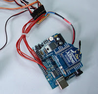
The transmitter is based on a Arduino Diecemilla with an Xbee shield and an Xbee pro. Stick are connected to the Diecemilla though a small board. The +5V and the ground wires are directly soldered on the Arduino and distributed to each stick through the small board (red and blue wire on the picture).


On the Shield, jumper must be set to PWR and XBEE.


The large vertical board above the battery is just to keep the Power Switch in place, there is no use at all of the electronic on this board. 5 cells are fine to power the Diecemilla and the Xbee.


The Xbees are preconfigured through a small adaptor board connected to the PC by USB. Baud rate must be set to 38400, no parity, 8 bits, no flow control. The rest of the settings can be found on the excellent french site o24rcp for the transmitter and for the receiver.


For the receiver, an Sparkfun Wee is connected to an XBEE: TX to RX, RX to TX, +3.3V and ground. Power is done by a 4.8v and a regulator to 3.3v, and digital output 0 to 6 to control the servos.

The software can be downloaded with avr-dude. Here is the hex image for the transmitter and for the receiver.
Protocol bewteen the 2 Xbees currently use 5 bytes including a CRC.

Have fun, do not hesitate to send me questions or tell me your feedback if you made something out of that.

15 octobre 2008

First fly - Premier Vol


Premier vol de mon vieux Yak avec une Radio perso. :)


Here is some video extracts of the first fly. Thanks to the Zhen who did take the video and pictures.


13 octobre 2008

First fly Soon !


After some fixes within the software, I am now getting closer to the first fly. I did some preliminary tests of servos and speed controller. All behaves good. The tail and rudder servos are bad quality and they move by small steps. But they behave the same than with a 12Z Futaba radio.
Speed controller are ok, and motor on seems to behave correctly. We'll see what happens when the model will be several ten's meter from the transmitter. First fly is coming soon !


The receiver has been quickly wrapped around with heat retractable scotch.

05 octobre 2008

Transmitter +receiver prototype first test at home

Here is a video showing the transmitter and receiver working. Transmission between transmitter and receiver is numeric. The receiver decode the servo position given in bytes and transform it in the right pulse and timing to move the servo.

A Prototype of the receiver


This is the prototype of the receiver. It is much too big and too heavy, but it's just a prototype. It's not easy to sold all this stuff. When mounting it, I made a mistake with the Wee board that I sold at the wrong position. I had to unsold it and to move it, it was quite a nightmare.

30 septembre 2008

Transmitter prototype


The transmitter is an old Graupner D14 box, with its sticks. All the original electronic has been removed. The prototype has 4 channels, but more could be added, up to 6 or 8. The case is even too big for this electronic.
It has very simple programmation, as there is no possibility to change any setting in the transmitter, except by reprogramming the Arduino :) More possibility can be added later, but for now let's "keep it simple".

The Arduino boards and the Xbee shields fit tightly on the top of the case.


It is powered with 5 cells to get above 5V, as required by the Arduino. Transmission speed to the receiver is 38400 bds, which make the servo moves reasonably smoothly.

Next step is to finish up the prototype of the receiver, and do some more tuning in the software.

16 septembre 2008

My first home made RC receiver


This is my very first home made RC receiver. It works on 2.4Ghz band, and can control up to 6 servos. It receives datas from the transmitter for servo position, but can also transmit back informations. As it is home made, it requires a special transmitter to work with. It keeps servo positions even if there is no transmitter. Later on fail safe will be added.

It is made with ready to use boards boards that you just need to fit together. There is no need to make PCB and solder components, just some soldering to adapt connections for the servos.
This is not yet a small receiver, but it can fit large models. It's about the size of the good old receiver that were made many years ago :). The next versions of the receiver will be smaller.

Here is small video showing servos moving around.

14 septembre 2008

Servos controlled remotely from a PC


Today, I have been able to control remotely servos from a PC through a pair of XBee modules.
On the receiver part I used an Arduino Dicemilla + XBee module and Futaba servos. This makes quite a big receiver to put in an RC modele, eheh, but hopefully the size should be smaller later on.

On the sender side, I used an Xbee Pro connected to the PC through the USB/serial cable. The PC sends commands such as "10400". The first number is the servo number, and the 4 other digits provide the servo position in hexadecimal.

The communication between the two Xbees is bidirectional, and allows many fancies that can't be done with traditional radios. For instance, during the test, I could get back information telling if the command has been successfully passed or not.

The nice thing about this, it that it all numeric: the sender sends pulse as number, the receiver receives pulse as number, and transform that to real pulse in time. Even if I stop the Xbee transmitter, the servo keep and hlod their current positions without any move. This makes easy to implement a failsave, where the servo go to a predefined position when no transmitter is detected.

The next step will be to couple the Sanguino with the Xbee to make the transmission part.

wee


ok, given than more and more people connecting to this blog are english spoken, I switch my blog to English. Sorry for french :), if there is something you want to ask, do not hesitate to ask your question in comments or by mail in French.
Yesterday I received my Wee from SParkfun. It's the same thing than an Arduino except that it is much smaller, has one or two analog entry less, and runs at 8Mhz. The Wee also runs at 3.3v, so that make easy to adapt it to an Xbee which is also 3.3v.
The benefit of the wee is that it's small, so coupled with an Xbee it could be used as a RC receiver.

11 septembre 2008

Commande des servos en parallele


Le soft pilote maintenant jusqu'a 8 servos, avec une precision assez bonne. Les servos ne grognent pas et se deplacent en continu d'un coté a l'autre selon mon petit programme de test. J'ai utilisé les interruptions avec un algo a ma sauce pour respecter au mieux les timings. Cela fonctionne bien pour l'instant, j'ai testé avec des servos futaba et un graupner. Le pilotage des servos se fait a partir de valeur numeriques, ce qui devrait permettre d'ajouter d'autres fonctions utiles comme le failsafe, ou le controle des gaz.

Le soft devrait pouvoir tourner sur un Tiny2313 ou similaire. Pour l'instant il fait 650 bytes donc il reste du gras.

A suivre: pilotage des servos a travers le XBee depuis un PC.

Oscilloscope


Pour "debugger" les problemes de timing pour le pilotage des servos, un oscilloscope est quand meme bien pratique. Seulement voila, ca coute cher ces bestioles pour un usage tres limité. Ou alors il faut avoir un copain pas loin qui en a un a vous preter, mais pas toujours facile d'avoir l'engin sous la main au bon moment.
La solution simple existe: utiliser le PC comme oscilloscope en entrant par la carte son. Rien de plus simple, il sufift de relier la prise micro de votre PC sur le signal a mesurer. C'est limité en frequence bien sur, mais ca permet de faire quand meme des mesures basiques.


Les softs: il en existe au moins deux sous Linux et une multitude sous windows. Sous linux, j'ai pu essayer xoscope. Il existe aussi osqoop qui est logiciel libre, mais ne marchait pas pour moi.
Xoscope m'a permis notamment de visualiser les trames et les interruptions.

04 septembre 2008

Xbee emetteur + Xbee recepteur


Les donnees sont envoyees par l'Arduino vers le XBee Pro a travers le port serie, puis le Xbee (Pro) envoie vers le second Xbee qui transmet alors vers le port serie du PC. Les connections series sont configurées a 9600 bps. Ca marche deja pas si mal!

03 septembre 2008

Potentiometre


Nouvel essai ce soir pour comprendre pourquoi les servos vibrent. En fait, le soft n'est pas le seul probleme. Il faut aussi une bonne alimentation des servos (evidemment) mais aussi un bon potentiometre. Le mien pas de tres bonne qualité oscille un peu et donc fait vibrer legerement le servo.
Le soft aussi: une simple boucle avec delay fonctionne bien, alors que l'utilisation de librairie servo fait vibrer le servo, et le neutre se promene un peu. A voir par la suite

02 septembre 2008

logiciels pour Arduino

Le plus simple pour programmer un Arduino est d'utiliser le soft Arduino. Il integre a la fois un editeur, un compilateur et le telechargement par le port usb/serie. Il y a du java quelque part, mais se base sur la toolchain gcc. Enfin c'est ce qu'ils disent dans la doc. L'avantage est qu'il existe pas mal de librairies qui simplifient beaucoup la tache, et permettre l'ecriture rapide de programme complexe.

Mais comme tout outil simple, il y a des inconvenient: relative lenteur de compilation, taille du code generée importante (environ 1k pour Blink), et moindre control du temps. De plus, si vous avez l'habitude d'un editeur type vi ou emacs, celui d'Arduino est tres primitif.

J'ai essayé de piloter 4 servos en utilisant les outils Arduino et la librairie de pilotage de Servos de playground. Resulat les servos "vibrent", sans doute a cause de l'envoi des trames par le microprocesseur qui n'est pas assez precis. Pour ameliorer la precision du temps, mieux vaut passer sur les outil gcc de base et avr-dude.

En utilisant les outils gcc-avr et l'excellent tutorial de avr freak, il devrait etre possible de gerer les trames envoyées au servo avec plus de precision.

J'ai suivi les instructions de cette page Program_Arduino_with_AVR-GCC pour installer, compiler et telecharger l'image dans l'Arduino. Ca marche parfaitement mis a part quelques parametres pour avr-dude qu'il faut regler, comme la vitesse de tranfert via le port usb/serie:

avrdude -p m168 -P /dev/ttyUSB0 -c stk500v1 -b 19200 -F -u -U flash:w:blink.hex


Le test du "blink" qui fait clignoter la led marche parfaitement, a condition de brancher la led au bon endroit. Attention car sous avr_gcc, les numero de port de sortie ne correspondent pas avec les numeros de Arduino et mieux vaut se referer directement a la datasheet de l'Atmel.

31 août 2008

Xbee

Voila ce que j'ai recu la semaine derniere:

27 août 2008

Etape 2

Finalement, je passe directement a l'etape "controle d'un servo par un potentiometre". Ca n'est pas tres compliqué, a condition de bien comprendre comment piloter un servo. Apres avoir essayé les differentes librairies Arduino ou Wire sans trop de succes (j'avoue ne pas avoir fait de test tres poussé pour comprendre ce qui ne marchait pas), j'ai finalement utilisé le code d'un autre blogger pour faire le test: http://www.flyingdahu.com/dotclear/?2008/01/03/23-electronique-ta-mere. Merci a Vincent.


Apres avoir essayé un vieux servo, sans trop de succes, le servo bougeait assez aleatoirement, je suis passé a un servo plus recent et de meilleure qualité. Les resultats sont bien meilleurs, le servo bouge bien dans les 2 sens aussi vite que possible en fonction de la position du potentiometre.
J'ai remarqué aussi que la tension fournie a travers le port USB pouvait etre juste suffisante parfois lors de mouvements rapides sur servo. En alimentant a travers une alimentation separée, avec un minimum de 7/8v le servo "tourne" bien, et a donc tout la puissance dont il a besoin pour bien fonctionner.

Coté environement de developpement, j'ai pas trop progressé. Arduino et Wire ne sont pas totalement compatibles et mieux vaut bien choisir ses librairies.

La prochaine etape va consister a envoyer l'entrée analogique vers un module serie type zigbee.
A suivre...

23 août 2008

Sanguino Montage

Et voila, j'ai enfin recu mon Sanguino. Enfin ca a ete assez rapide, a peine plus d'une semaine. Voila donc les composants recus:


En suivant les instructions de la page http://sanguino.cc/1-0kitassembly c'est tres simple a monter, il faut moins de 2 heures. Mieux vaut avoir une panne de fer a souder fine, car certains trous sont a peine etamés sur le dessous.
Voila ce que ca donne:

Ensuite, vient l'heure du premier test: il faut brancher sur le port USB. Mais d'abord, telecharger le soft Arduino, puis installer les fichiers Sanguino comme indiqué sur la page Sanguino. Ensuite il n'y a plus qu'a brancher le port USB, ou eventuellement Windows installera les pilotes manquants. Ensuite, apres avoir lancé le soft Arduino, il faut configurer le type de board (Sanguino) et le port serie. Pour le premier test, j'ai essayé l'exemple disponible dans l'environement Arduino pour allumer une led. Si le soft est bien configuré, tout se passe tres simplement. La premiere fois, il suffit de clicker "upload" et tout se passe. Les fois suivantes, il faut appuyer le bouton reset d'abord, et ensuite click upload pour que le chargement se passe. ensuite j'ai joué avec le programme pour faire clignoter 4 leds. Voila une photo:


Tout ceci marche fort bien pour l'instant. L'environement de developpement Arduino d'origine fonctionne bien sous windows. Il me reste a essayer sous Linux, avec un environement plus puissant et qui me permet d'utiliser mes outils favoris surtout pour l'editeur de code (vim, make, avrdude, ...).

La prochaine etape sera de connecter un potentiometre et faire allumer ou eteindre les leds selon sa valeur.

18 août 2008

Sanguino

L'Arduino, vous connaissez ? C'est un petit microcontroller pratique pour de petites application electroniques. Il se programme facilement par un port USB en Gnu C avec un environnement de developpement totalement libre.
Choisir le bon microcontroller n'est pas toujours simple, le choix est vaste. J'ai trouvé qur cette page quelques indications utiles: Choisir un microcontroller (anglais).

L'atmel a des avantages, notamment des instructions puissantes et une stack en SRAM donc non limitée a priori. Gnu C est aussi disponible, ainsi que les outils libres.
Voila quelques applications sympas developpées a base d'Arduino:
Et comme mon projet dont je vous parlerais plus tard necessite plus de SRAM et de flash, j'ai choisi de commander ceci: sanguino equippé de l'Atmel 644P.
Mais est-ce qu'un processeur 8bits avec 64Ko de flash et 4ko de Ram suffira a mon projet ?
La prochaine etape des que j'aurais recu la bete sera la mise en route et le telechargement d'un programme simple avec avrdude.
A suivre, donc,

Bonjour,

Bienvenue sur mon blog.
Vous pouvez aussi consulter mon site web consacré au modelisme et au F3F: http://obor.free.fr