23 août 2017

Bed adherence

After years of using blue tape for bed adherence, I decided to try something else which do not make any mark below the print and which would work at least for PLA and PETG...
So, my friends of the Grenoble maker club, recommended me to try using mirror  with head spray. They advertise it me so well that I decided to try.

As I had some old mirrors around, with good  dimensions, I simply lay one done on the Tevo Tarantula aluminium bed (without the PEI) and fix it with clips. Then I spray the surface with hair spray .
That's all.

First test with PLA succeed with no problem, the bed was a 50°C, adherence was great , no warping nothing. After print is finished, then I needed to wait until the bed is completely cold, or put the mirror + parts  into a fridge. When cool the printer part can be very easily removed.

Then I tried exact same method with PETG, with bed heated at 75°. It also works great ! The part I tested was  7x5cm so not very large, but it worked fine. Same as for PLA, wait until the bed is completely cold to remove the printed part.

In addition, the mirror surface is perfect, and bed can then be easily leveled.
So all benefits, I think I  can now forget the blue tape ... ;)


14 août 2017

Vibration, ripple, shadow, ghosting

I have own several printers and the ripple effect always  appears on most of my print.
How to get rid of it ?

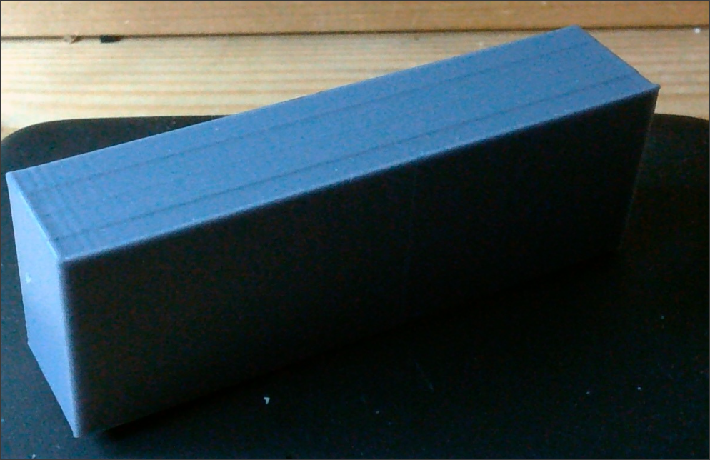
The ripple or vibration or shadow effect looks like this:


Look on the surface where it is bright, do you see all this little waves ? They are vertically aligned. The surface should be perfectly flat and clean.
This test has been printed with my last printer, home made, see TevoTarantula in an earlier post.

Thanks to "megablue" who did post this very demonstrative test. You can find it here on thingiverse.

To remove this effect, I tried several things: switch from delta (the worse for ripple effect) to Prusa, change rods on OboXL3D (big ultimaker like), switch from bowden extruder to direct, switch from Direct to the E3D Titan Aero...

Here is the list, mechanical, electronic and settings:
- belt tension
- axis movement softness
- remove any play
- replace motor (Nema 17 1.8° and 0.9° per turn)
- stepper driver (A4988, DRV8825, TMC2100)
- various electronic boards (Mks base 1.3, MKS base 1.5, MKS SBASE, Arduino + Ramps, etc...)
- frame: delta(Kossel XL), ulimatker like, Tarantula Tevo (prusa), Minifab, Anet 3d(prusa), TevoTitan(prusa)
- bowden to Direct extruder
- Direct extruder to Titan Aero
 
Settings:
- decrease X, Y acceleration
- decrease X, Y jerk
- Increase E jerk
- increase E acceleration
- reduce X,Y max speed


My last print improved, even if not perfect. What I changed ? Filament mainly...
Here is the result:

So to conclude, it seems that the best solution is still to reduce speed as much as possible, and avoid abrupt acceleration as much as possible, because the extrusion can't handle it quick enough..
Do not hesitate to post a comment below if you want, there is may be a good solution to make technical parts looks better.

09 août 2017

Testing a very low cost powerfull chinese servo MG996R...

Well, I am dispointed by this very low cost chinese servo MG996 , which is supposed to provide a 9kgcm torque...
https://goo.gl/eKHo4n
It is less powerfull than a Hitec 5485HB   with 6.5kgcm....

In fact, both servos do not comply specifications announced, even the hitec one. Be warned.
But the Hitec is still better, with less power consumption.

See the videos of the various tests:

MG996 + 2kgcm
https://www.youtube.com/watch?v=FhIateV-FQM
MG996 + 4kgcm
https://www.youtube.com/watch?v=KSFvNfwC1hQ
HS5485HB + 2kgcm
https://www.youtube.com/watch?v=BgbTJ_VrUpo
HS5485HB + 4kgcm
https://www.youtube.com/watch?v=akFqISy-pBU
HS5485HB + 6kgcm
https://www.youtube.com/watch?v=_jBK-Rj3CDE

06 août 2017

GT2 pulley

After some search I found this way to make a pulley of various size , for a GT2 belt with a 2mm  pitch.

First, you need to know the number of tooth, and the pitch of one tooth (2mm ). Then compute the diameter of a circle which will contain a polygon. The side of the polygon is the pitch, and the number of side of th epolygon is the number of tooth. This site is great  to help that computation:
https://www.calculatorsoup.com/calculators/geometry-plane/polygon.php
otherwise this formula:
Inradius r
  • r = (1/2)a cot(π/n) = R cos(π/n)
where r  is the distance between the center of wheel, and the nearest point of the side, and n the numer of sides of the polygon:

 
Once r value is found, then the wheel can be created under CAO software with this method:

1) make a solid wheel a little bigger than r, thinckness 8mm is fine for GT6
2) extrude draw on the surface , one tooth  like this:


The distance between both extrmimites of the tooth should 2mm. The diameter should be .78.
The center of the circle should be at r distance from the center of the pulley. 
3) do a circular repetition of the function , based on the center of the wheel
4)done